Scaffolding hop-up bracket tie bars
Tie bars are provided on two and three board hop-up brackets to prevent the brackets rotating (i.e. splaying) and to prevent planks becoming dislodged and falling.
As well as preventing planks from falling, the tie bar should be designed and installed so that the risk of the tie bar becoming dislodged and falling is minimised.
An example of a tie bar on a two-board hop-up bracket is shown in Photograph 1. This information focuses on the issue of inadvertent dislodgement of the tie bar and sets out minimum benchmarks.
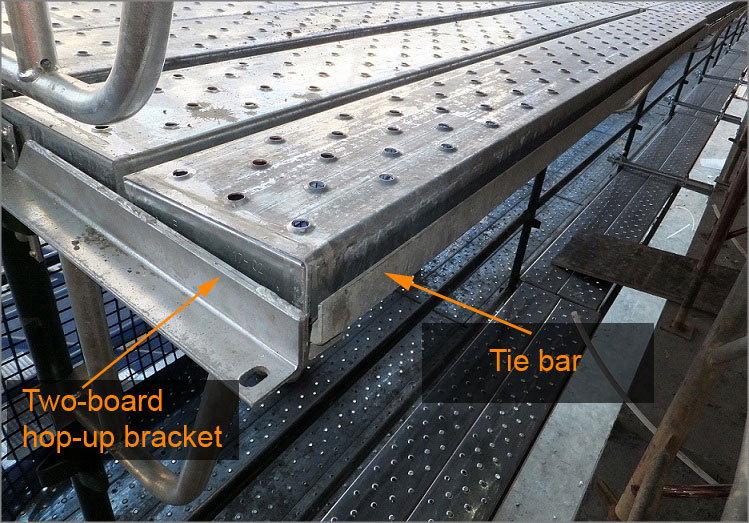
Photograph 1: Two-board hop up bracket and tie bar.
There have been a number of incidents in Queensland where tie bars have become inadvertently detached and workers have either fallen or been struck by a falling tie bar.
Any single inadvertent force should not be able to dislodge any part of the tie bar. For example, a bouncing motion caused by an object falling down on the scaffolding deck or an inadvertent vertical or horizontal force should not be able to dislodge the tie bar.
The locating pins on tie bars are generally of two types:
- Straight pins
- Pins with a 45 degree bend half way along the pin.
Pins with the 45 degree bend are usually more effective at helping to prevent inadvertent dislodgement of the pin, particularly when the pin is inserted so that the end of the pin points back towards the scaffolding (refer Photographs 2 and 3).
The issue of inadvertent dislodgement of tie bars is not specifically discussed in the Queensland Scaffolding Code of Practice 2021 (PDF, 1.75 MB) (the code).
A platform bracket shall be designed so that it cannot be accidentally dislodged or rotated when in use.
Similar principles can be applied to tie bars.
When installing platform brackets, make sure that they are interconnected with a tie bar and that the open side of the tie bar angle faces inwards, enabling the steel plank to sit in the angle. This prevents accidental dislodgment of the tie bar.
Position of tie bars
Any tie bar should be installed so that a single distinct action, without a scaffolding plank sitting on top of the bar, cannot dislodge any one pin on the tie bar. Where the scaffolding manufacturer specifically provides documented instructions on the correct installation of tie bars, these instructions must be followed. In the absence of these instructions, below are a number of examples showing preferred practices and unsafe practices. Not all examples may be highlighted, but the same principles can be used in other scenarios.
In addition to minimising the risk of falling scaffolding components, the design of the hop-up bracket and tie bar should also reduce the gap between planks. Section 5.7 of the code specifies for working platforms that no single gap between planks exceeds 25 mm and the total gap between all planks does not exceed 50 mm.
Example (a) - Preferred
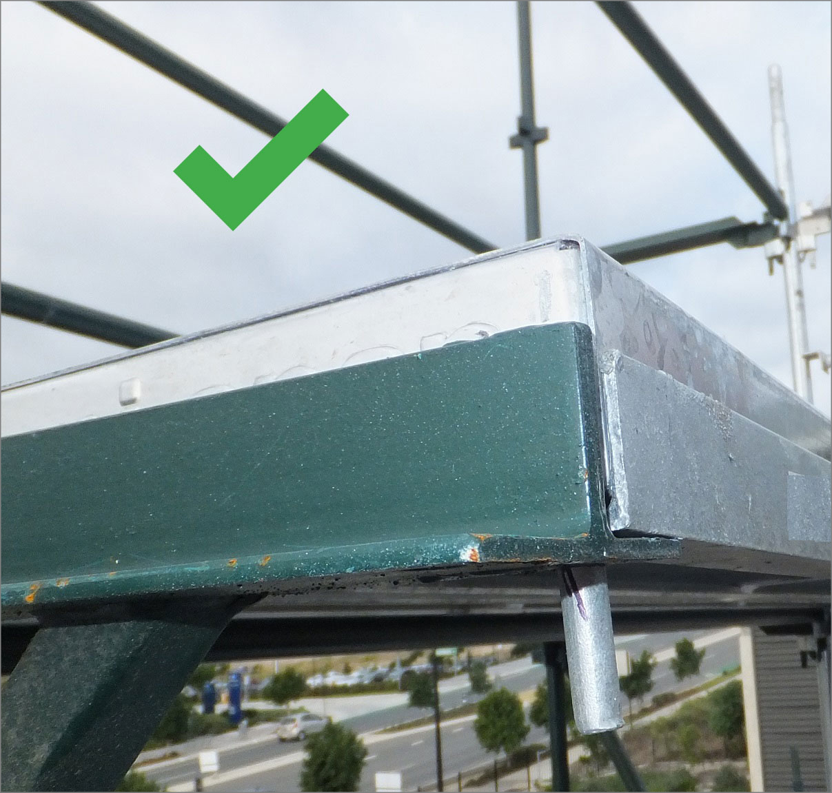
Tie bar pins with 45 degree bend with end of pin pointing back towards scaffolding.
It is acceptable for the scaffolding plank to be either on top of the horizontal part of the tie bar (refer Photograph 2) or next to the tie bar (refer Photograph 3). When next to the tie bar, the tie bar can either face inwards or outwards (refer Photograph 4). In all of the examples, the tie bar should not become dislodged with one single action. If the tie bar is rotated backwards it will strike the plank.
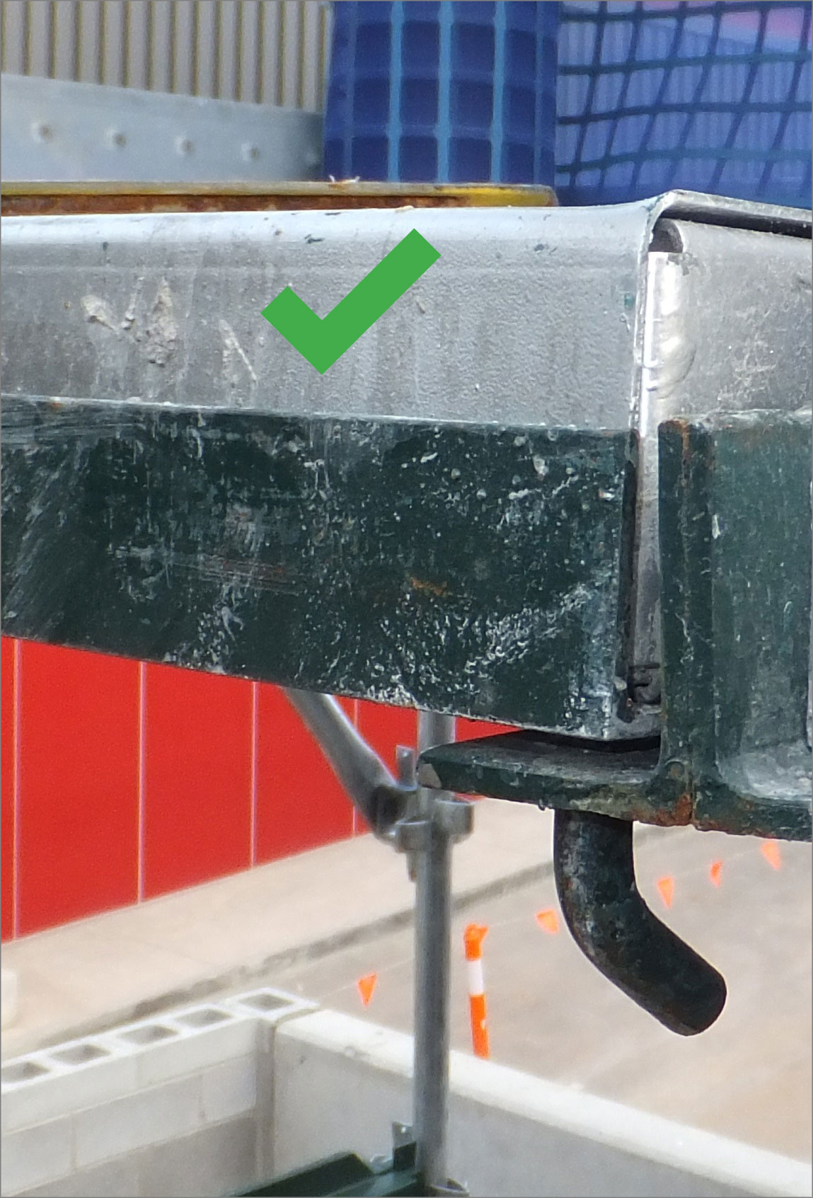 Photograph 2: Pin pointing back to scaffolding with plank on top of tie bar – preferred. | 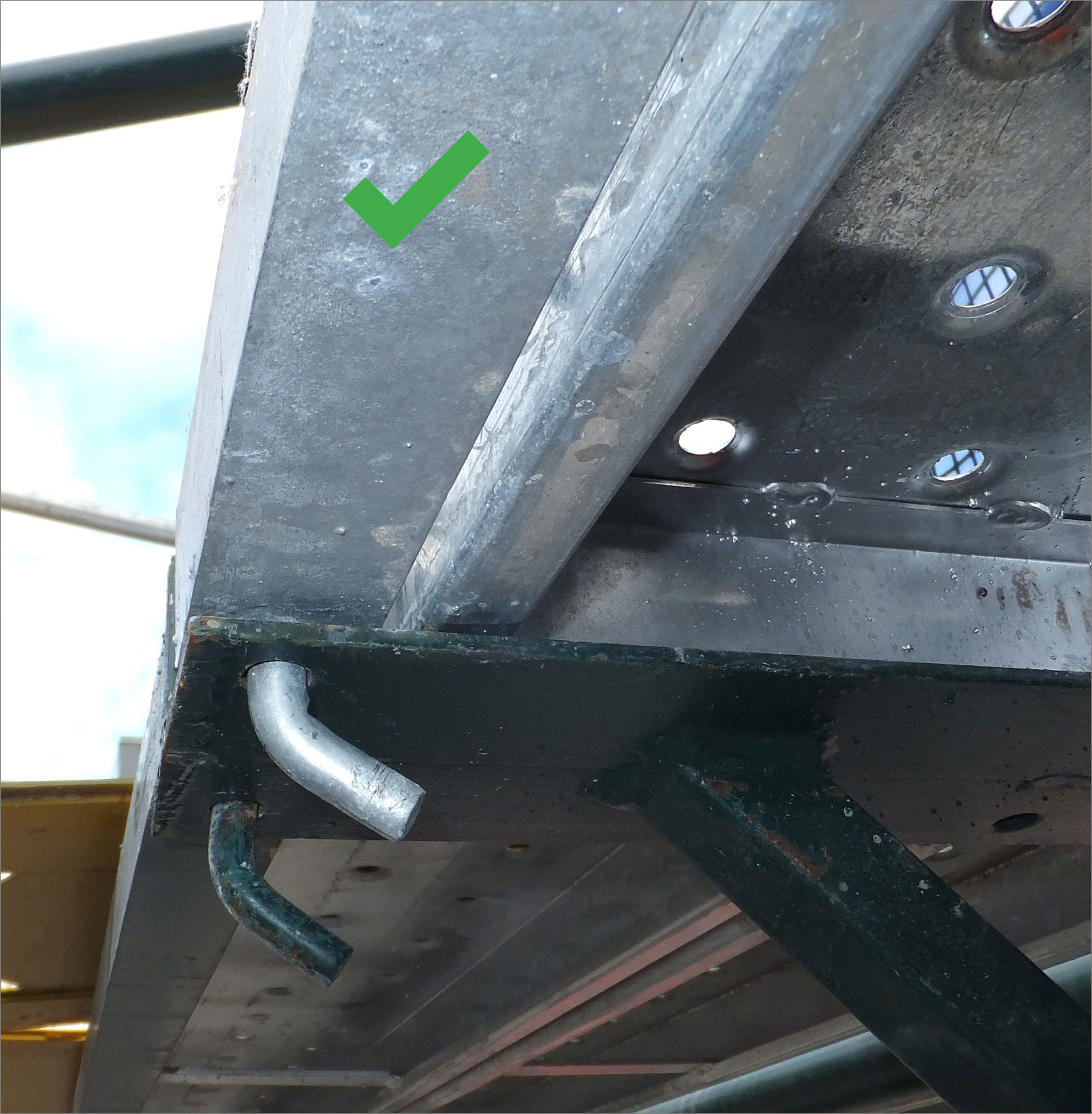 Photograph 3: Pin pointing back to scaffolding with plank next to tie bar – tie bar angle facing inwards - preferred. |
|
Example (b) – Preferred
Tie bar with straight pins.
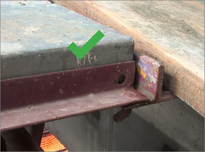
The scaffolding plank is positioned on top of the horizontal part of the tie bar with the plank pushed up against vertical face of the tie bar (refer Photograph 5). In this example, the tie bar is unlikely to become dislodged as both the tie bar and the plank would have to be pushed up vertically at the same time.
Photograph 5: Tie bar with straight pins and plank sitting on tie bar – preferred.
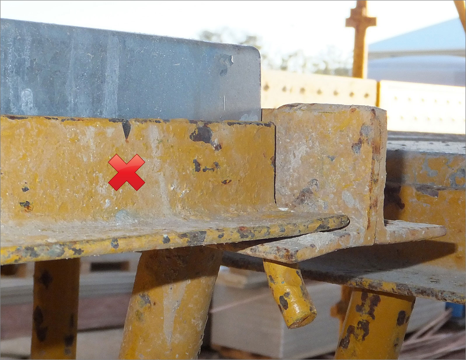
Example (c) – Unsafe
Tie bar with straight pins.
Scaffolding plank is positioned next to but not on top of the tie bar (refer Photographs 6 and 7). In this example, the tie bar can become dislodged if the bar moves vertically and the plank does not resist movement.
 Photograph 6: Tie bar with vertical pin and plank next to tie bar (tie bar installed facing forwards) – unsafe. | 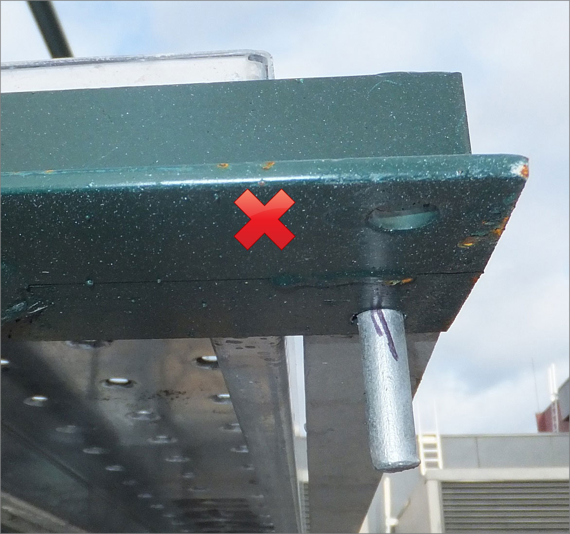 Photograph 7: Alternate view showing tie bar with vertical pin and plank next to tie bar (tie bar installed facing forwards) – unsafe. |
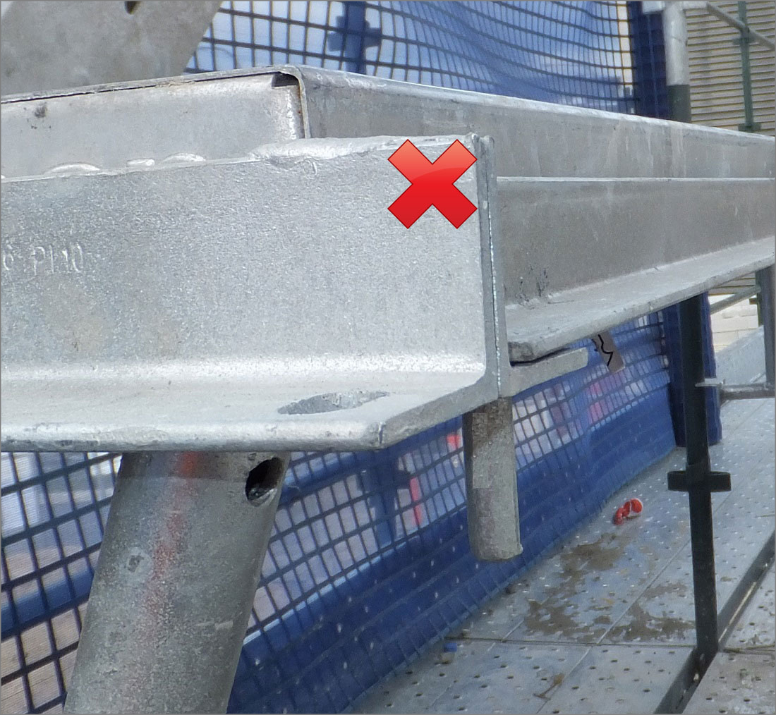
Example (d) – Unsafe
Tie bar pins with 45 degree bend with end of pin pointing away from scaffolding (refer Photograph 8). In this example, the tie bar can become dislodged if it is rotated forwards. There is no plank to resist this movement.
Photograph 8: Pin pointing away from scaffolding with plank next to tie bar – unsafe.