Hung scaffold collapse
Issued: 21/06/2023
Last Updated: 21/06/2023
Purpose
This safety alert discusses the collapse of a hung (drop) scaffold and risk control measures to prevent similar incidents in the future.
Background
In February 2023, three sections of a hung scaffold collapsed, dropping scaffold components and stacked materials to the ground. The scaffold was under a rail bridge (refer Figure 1) and was to be part of larger installation that would fully contain the bridge for repainting. The collapse occurred at night and fortunately no workers were on the scaffold. The scaffold had not yet extended over water and the collapse was limited to a fenced area not accessible to the public.
Contributing factors
The cause of the incident is being investigated and several factors may have contributed to failure of the structure.
Action required
The following information provides guidance on the design, erection, and use of hung scaffolds.
General
Hung scaffolds differ from traditional ground supported bay scaffolding in significant ways. These differences pose challenges for scaffold designers and the scaffolders.
Support
Apart from the support being from above than below, large work areas on hung scaffolds may have limited support hangers spaced further apart. This results in less opportunity for alternative load paths should a primary support component fail.
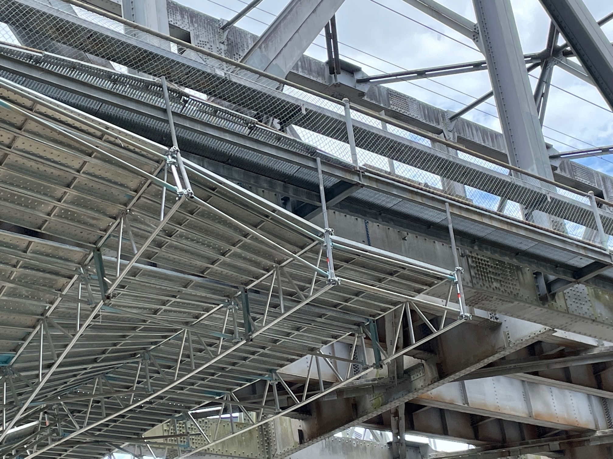
Figure 1 - View showing part of hung scaffold involved in incident (end that remained intact)
Component integrity
Components for any scaffold need to be of good quality and be in good condition free from defects, damage, and corrosion. Components, including those that transmit loads to the support positions, should comply with the manufacturer’s design specifications. All welds on trusses and ladder beams should have the correct size, degree of penetration, and be free of cracks. Trusses require all joints to be sound, as the position of maximum joint load will vary depending on how the scaffold is loaded.
Working load classification
On traditional independent scaffolds, the concept of bay size is straightforward, being the platform area between four standards. Design loadings for scaffolding are specified both in the Scaffolding Code of Practice 2021 (PDF, 1.75 MB) and Australian/New Zealand Standard AS/NZS 1576.1-2019 Scaffolding Part 1: General requirements. Both the Code and AS/NZS 1576.1 specify allowable scaffold loads by the maximum allowable total load per bay and a concentrated point load. For example, the heavy-duty classification requires total load of 675 kg (6.6 kN) per bay per working level, including a concentrated load of 200 kg (2 kN). For a typical bay of 2.44 m length that is five planks wide (i.e., 1200 mm wide), the total load of 675 kg is equivalent to approximately 2.3 kPa. Thus, a heavy-duty load rating is a good indicator that the scaffold can withstand this level of ‘partial area’ load in a regular pattern.
Specifying loads-per-bay for large area hung scaffolds is not useful, and the loading classifications of light, medium and heavy are largely inappropriate. The working load classification specified for a hung scaffold should accurately reflect the way the scaffold is to be built and used. The classification should be in a form that both scaffolders and workers using the scaffold can understand.
AS/NZS 1576.1 uses the terminology of ‘Special Duty’ for a specific total load, and ‘Special Work Zone’ for a specific area over which the special duty load is applied. The special duty classification in AS/NZS 1576.1 also requires nomination of a ‘Partial Area’ load in addition to total load for the special work zone. For large area hung scaffolds, even this concept needs to be extended to consider the possibility of multiple partial area loads and the resulting effect on the primary members.
Loadings - stacked materials and installation
Packs of scaffold components are sometimes loaded onto a scaffold under construction either by hand stacking or directly by crane. This may also be the situation with some hung scaffolds. The scaffold must safely withstand loads applied by the packs including dynamic factors if a lifting device is used. The scaffold designer needs to consider the designated ‘partial areas’ where packs are to be placed, and design the scaffold structure to resist the maximum effects of these loads.
For example, planks are often delivered in packs of 40 to 50, depending on the plank specification. A pack of planks landed on the scaffold deck could apply an evenly distributed load of approximately 3 kPa (i.e., 300 kg/m2) to part of the hung scaffold. For this example, the partial area where the packs are landed needs to be designed to resist a working load of 3 kPa and additional potential impact factors.
For scaffold loading platforms, the Code specifies a design loading of 5 kPa with an impact factor of 1.25. It’s acknowledged that building a complete hung scaffold to safely withstand 5 kPa will usually be impractical because the supporting beams would become too large or require too many hangers. The structure from which the scaffold is suspended may also not be strong enough. However, the high loading specified for loading platforms in the Code, illustrates the point that loads applied by stacked materials can far exceed the loads applied to the scaffold in normal use. The scaffold designer not only needs to consider the effects of single areas of stacked materials, but also the combined effect when other locations are loaded by materials and scaffolders at the same time in a ‘patchwork’ of loading.
The designer should specify the location and working capacity of partial areas and the number and pattern of active areas allowed at the same time. The influence from combinations of such loads on the support components in the scaffold should be considered in the design. To reduce the possibility of any confusion, the loading areas should be identified both on the scaffold drawings and by physically marking or fixing signs to the areas on the scaffold, during the erection phase. Colour coded loading zones can assist in communication.
Loadings – in use
The scaffold must also safely withstand working loads applied by workers, equipment, and the work process itself following hand over. The scaffold designer needs to consider both the effects of evenly distributed loads applied to the deck such as water or debris build-up during the work activity, and localised loads from workers and plant. The working loads specified by the designer need to be marked on the drawings and identified by signs fixed to the completed scaffold. As an example, if a localised maximum live load of 3 kPa can be applied by the work activity then the design and design documentation should reflect this and any conditions on positioning and spacing of such loads. Working loads marked on the scaffold should be in a form that is readily understood by scaffolders and workers (e.g., 100 kg/m2 as an approximation instead of 1 kPa).
Suspension points
Suspension points and the load transferred to the overhead structure should be assessed by the scaffold design engineer in consultation with the structure owner. This may require additional engineering assessment of the overhead structure based on the original design, along with a condition assessment of the structure (e.g., including effect of corrosion and other degradation of the structure).
Truss and ladder beams as primary support components
Hung scaffolds typically use trusses, or ladder beams, that are hung from suspension points either using scaffold tubes or purpose-built hangers. The scaffold designer needs to calculate or otherwise verify the effect of the way the trusses are suspended. A scaffold drop tube is typically attached to both top and bottom truss cords with couplers, whereas a suspension bracket design might only contact the top or bottom cord.
Trusses and ladder beams are typically installed with bracing to resist buckling of compression chords and twisting of the beam out of the vertical plane. The specified bracing should comply with the truss or ladder beam supplier’s instructions where provided.
Some hung scaffolds include trusses or ladder beams that have both internal and cantilevered spans. Where this is the case, the scaffold designer needs to take into consideration the different action effects depending on how the deck is loaded. For example, the top chord of a truss may change from being a compression member to a tension member. Also, the relatively low span to depth ratio of typical scaffold truss accessories can result in the shear action being the first limit to capacity.
Mix and matching
It is generally preferable for scaffold components from a single manufacturer to be used on a scaffold as the design is more likely to be tried and tested. Mixing and matching can introduce additional design issues that could detrimentally affect the safe performance of the scaffold. However, where mix and matching of components does take place, the scaffold designer needs to consider any adverse design effects and how these can be addressed. It should also be noted that where a scaffold company decides to use a single scaffold system from one manufacturer, warranty claims would be more easily justified. Mixing and matching of scaffolding systems is outlined in Australian/New Zealand Standard AS/NZS 1576.1-2019 Scaffolding Part 1: General requirements.
Other loading considerations
The scaffold designer needs to consider other loading applied to the hung scaffold during its complete life cycle. Wind loading is more significant where the scaffold is encapsulated. Cyclic loading or vibration may be present, such as on bridges with vehicular and train traffic. Some additional component loads, or load factors, may need to be applied to allow for these additional loads. For encapsulated scaffolds, water build-up from rain should also be considered in the design. Information on wind loading is provided in Australian/New Zealand Standard AS/NZS 1170.2-2011 Structural design actions: Part 2 Wind actions.
Communication between the designer, scaffold company, and scaffolders
It is important that, prior to building the scaffolding, scaffolders clearly understand how the scaffold is to be erected. This includes the sequence of erection and how scaffold materials are to be stacked on the scaffold. It is recommended that the scaffold designer endorses the scaffolding erection procedure. Prior to issuing instructions to the scaffolders, the company tasked with scaffold erection should check all documentation to verify information is complete and clearly communicated.
Scaffold design drawings provided to the scaffolder should clearly show where materials and scaffold component packs can be landed. Scaffolders should also be given clear, documented instructions on the sequence of installation. It is generally not adequate, to expect a scaffolder with a high-risk work licence alone to understand how to safely erect a hung scaffold, unless they can demonstrate previous experience. Where a scaffolder lacks appropriate experience, they should work under the supervision of a scaffolder with that experience.
In some situations, the true condition of the structure, from which the scaffold is to be hung, cannot be seen until the scaffolders are ready to erect the scaffold. One example is a hung scaffold in large boilers where the scaffold is hung off boiler tubes. In these situations, an engineer may need to carry out progressive internal inspections of the supporting structure to confirm it is structurally adequate as the scaffold is built.
Further information
- Scaffolding Code of Practice 2021 (PDF, 1.75 MB)
- Australian/New Zealand Standard AS/NZS 1576.1-2019 Scaffolding Part 1: General requirements
- Australian/New Zealand Standard AS/NZS 1170.2-2011 Structural design actions: Part 2 Wind actions.
- Work Health and Safety Regulation 2011