Lifting inserts for tilt-up and pre-cast concrete construction
Issued: 10 December 2009
Last Updated: 11 December 2009
Purpose
Lifting inserts are specially designed and manufactured items, of controlled strength and ductility, which are cast into concrete elements for the purpose of lifting.
The purpose of this safety alert is to help minimise the likelihood of lifting insert failure in tilt-up and pre-cast concrete elements.
Background
In Queensland there have been failures of cast-in lifting inserts in concrete elements. These incidents include failure of the concrete surrounding the lifting insert and failure of the insert itself.
The potential risk to life from failed lifting inserts can be considerable due to the large size and weight of some concrete elements involved. Concrete elements include a wide range of products including wall and floor panels, bridge beams, road barriers and culverts.
A compatible lifting clutch, designed for use with a particular lifting insert is attached to lift the concrete elements into place. There are two common types of proprietary lifting inserts:
- Round bodied anchors for general use.
- 'Hairpin' plate inserts for edge lifting, with and without a hole for attaching extra reinforcing.
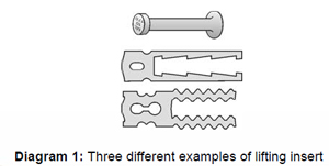
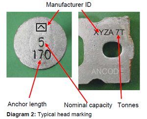
Diagram 1 shows three examples on the above listed common types. Diagram 2 shows typical head markings on inserts.
Failures can occur when anchors do not meet the design engineer's specifications for the element to be lifted or are incorrectly installed.
Where anchors are located in the edges of thin elements, the failure of the concrete surrounding the anchor may limit the working load. Therefore the nominal anchor capacity marked on the anchor head, may not be achievable.
Factors resulting in failure include the following:
- inadequate concrete strength and curing times
- the use of the incorrect type and model of lifting clutches for the specific lifting insert
- the use of the wrong type of lifting insert
- inadequate anchor embedment depth
- inadequate concrete compaction (particularly around the lifting insert)
- incorrect anchor reinforcement
- incorrect or damaged void formers
- incorrect slinging configuration for the lift
- using defective lifting inserts or inserts with insufficient strength
- applying inappropriate shock loading when lifting or moving the concrete element due to poor rigging practices, panel handling or panel preparation (i.e. not using an effective bond breaker).
Recommended control or prevention measures
Lifting insert failure can be avoided by correct engineering and installation combined with correct lifting procedures and supervision. Control measures that will reduce the likelihood of failure are discussed below.
Lifting insert and clutch specifications Lifting insert systems should have a minimum guaranteed factor of safety of 2.5 to 1 against failure of the anchor, the concrete, or any reinforcing to which the insert relies upon for its anchorage. For instance, an insert for a 10 tonne working load must not fail at less than 25 tonnes when installed in accordance with the manufacturer's and engineer's specifications.
Lifting clutches should have a minimum factor of safety of 5 to 1 against failure.
Manufacturers of lifting inserts and clutches require quality assurance systems to ensure that these factors of safety are consistently achieved.
All lifting inserts and clutches should be permanently marked with the nominal capacity of the anchor in tonnes and the manufacturer's identification mark. These marks should be visible when the anchor is placed in concrete.
Engineer design for lifting Engineers responsible for designing the concrete element lifting systems are to use relevant technical standards and sound engineering principles when specifying reinforcement in the concrete element.
Concrete elements should not be lifted unless the engineer has verified the panel design for lifting1. The engineer's verification is to include a statement that the design complies with AS 3850 Tilt-up concrete construction for both in-situ loads and erection loads. The engineer's certification can be provided on the concrete element drawing or a separate letter that refers back to the element design drawings.
The design is to ensure that loads applied to the lifting inserts during lifting do not exceed either the capacity of the concrete, the insert or the reinforcement required for the anchorage. The erection engineer should specify the rigging set-up and crane type for lifting the element.
On-site quality assurance Verification that the concrete element has been constructed in accordance with the design is to be carried out. Design drawings and engineering certification are to be kept on site.
Prior to lifting the element, the following points are to be verified:
- each concrete element has been constructed in accordance with the engineer's design, and
- the concrete is the required strength for lifting.
Wherever the design of the element (i.e. including the lifting insert specification and/or the location) is altered the alterations are to be approved by the erection engineer.
Note1: wall panels and braces also need to be certified by an engineer for wind loading.
Further information
Further information on safety issues relating to tilt-up and pre-cast concrete is provided in the Tilt-up and Pre-cast Construction Code of Practice 2003 (PDF, 0.96 MB).