
Zip line (flying fox) terminations
Issued: 9/12/2019
Last Updated: 11/08/2026
Purpose
The purpose of this safety alert is to inform zip line owners, operators, engineers and riggers of the risk of failure of zip line terminations and to provide guidance to help prevent the failure of zip lines.
A zip line consists of a steel wire rope that is suspended between two points, along which one or more people travel while suspended from trolleys. Zip lines are also known as flying foxes.
This safety alert provides information on zip line terminations and does not apply to other suspended rope applications.
Background
In October 2019, an 86-metre zip line termination failed and two patrons dropped to the ground, causing fatal injuries to one and serious injuries to the other. The two patrons were travelling along the zip line, one behind the other, with a rope link between them.
The zip line termination that failed used wire rope grips (e.g. bulldog grips, refer photograph 1).
Wire rope terminations on zip lines now typically use pressed ferrule or swage-type rope terminations (refer photograph 2)1.
Both pressed ferrule terminations and wire rope grips rely on the application of pressure between two parallel sections of wire rope, the rope tail and the loaded section. The applied pressure creates frictional resistance to avoid failure of the termination by preventing relative movement. However, wire rope grips on zip lines are unacceptable due to a number of weaknesses discussed later in this safety alert.
Visual inspection of rope terminations may not be adequate on its own as a means for verifying the ongoing adequacy of terminations.
The rope tension in zip lines can be extremely high and includes:
- pre-tension applied to the rope during set up (to reduce sag, i.e. 'catenary')
- tree movement and wind
- temperature changes
- the additional loads applied by patrons using the zip line
- additional loads imposed during a rescue.
It is important to note that loads applied by patrons to the zip line and its end anchorages will be many times their self-weight due to the triangulation effect of the load. For example, if a 100 kg patron uses a zip line, the additional tension applied to the zip line and its anchorages could be more than five times greater (i.e. potentially in excess of 500 kg force).
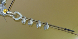 Photograph 1: Rope termination using wire rope grips bulldog type (example only) | 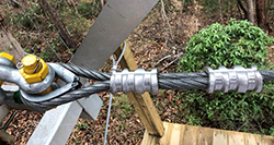 Photograph 2: Pressed swage type rope termination (example only) |
Contributing factors
The 2019 incident occurred due to failure of the wire rope grip type termination at the top end of the zip line, allowing the zip line to disengage suddenly and causing both patrons to fall to the ground.
Action required
Australian Standard AS 2316.2.1:20161 applies to the design and construction of zip lines. There are several other Australian Standards relating to lifting and rigging gear that provide information on design and testing. The principles in these standards can also be applied to zip lines.
All zip lines
All zip lines, including the zip line terminations and anchorage systems, should be designed or verified by a suitably qualified Registered Professional Engineer of Queensland (RPEQ). The engineer should verify all components of the zip line including the methods used to install the hardware. The engineer should provide written instructions on periodical inspection methods for the zip line along with any limitations on its use (e.g. loading, wind).
All connections should comply with recognised Australian or International Standards for lifting or climbing equipment. Connections should also comply with sound rigging practice. This includes setting up zip lines using:
- thimbles on all steel wire rope terminations
- load-rated and moused shackles (i.e. to prevent the pin coming loose)
- load-rated chain that has been proof loaded before use
- load-rated turnbuckles and connectors.
Hand spliced terminations should not be used for zip line terminations. A termination must not be used if the termination manufacturer states that the termination is unsuitable for suspending people. Any conditions that a termination manufacturer states for the use of a termination should be complied with.
Zip lines are to be installed by workers who hold a high-risk work licence in advanced rigging.
An assessment of all trees to which zip lines are attached should be made by a qualified arborist prior to commissioning and at intervals not exceeding 12 months.
Zip lines should receive a safety inspection by a competent person after high winds (specified by the engineer) or other severe weather events, especially where one or more of the end anchorages is on a tree. Tree inspections should be carried out by an arborist.
Further information on inspection of high ropes courses is provided in AS 2316.2.2:2025.
Design loads
The zip line installation, including rope terminations and anchorages, should be designed for a safety factor of at least 5 to 1 with respect to the maximum rope tension in the zip line wire rope. The maximum rope tension in the zip line is the sum of all loads, including, but not limited to, the following:
- Rope tension due to application of the maximum rated capacity of the zip line (i.e. tension due to the maximum weight that can be suspended and run along the zip line).
- Zip line rope tension due to self-weight and catenary (i.e. pre-tension).
- Environmental factors (wind loads, tree sway, etc).
AS 2316.2.1-2025 provides more detail on the design of the zip line and its anchorages. AS 2316.2.1 requires samples of critical assembly terminations, including the backup assembly, to be tested to destruction to determine the working load limit WLL (e.g. type testing). Designers, manufacturers and suppliers of zip lines and zipline components must provide information about the results of testing, and this information should be reviewed by the design verifier.
Test loads
Prior to its first use, a proof test load should be applied to the zip line in the same manner that the zip line is to be used. A minimum proof-test load of twice the rated capacity of a zip line is recommended. Two examples of how the test load is calculated and applied are shown in examples 1 and 2.
If an engineer wishes to replicate this test with a pull test (i.e. due to the difficulty of transporting and applying test weights), this can be done, provided the alternative method accurately replicates a test load of twice the rated capacity of the zip line. If a pull test is selected, the engineer is to carry out a detailed mathematical analysis to demonstrate the alternative testing method will provide a test load equivalent to using test weights suspended from the line that are twice the rated capacity of the zip line. It is advisable that the analysis includes a comparison between the calculated pull force versus suspending test weights on the zip line. The analysis must demonstrate that the test weights and pull test are equivalent. If a pull test is carried out, the test is to be applied in both directions on the zip line.
After the proof test and prior to use, the zip line installation should be inspected to check for damage and other irregularities, including slippage of rope terminations. Inspection should only be carried out by the engineer or workers with a high-risk work licence in rigging, with guidance sought from the engineer.
Periodic load testing (using a test load of 2 x rated capacity) of every zip line, and post-test inspection should be carried out at intervals as specified by the design engineer but should not exceed 12 months. Persons carrying out the load test and post-test inspection should be riggers or engineers.
Worked examples – Calculation of proof test load
Example 1
The zip line has a rated capacity of one person and is based on the mass of the person, harness, trolley and connection hardware not exceeding 135 kg (e.g. actual mass of the patron alone not to exceed 125 kg)2.
Proof test load = 2 x 135 kg = 270 kg suspended on one zip line trolley (refer Diagram 1).
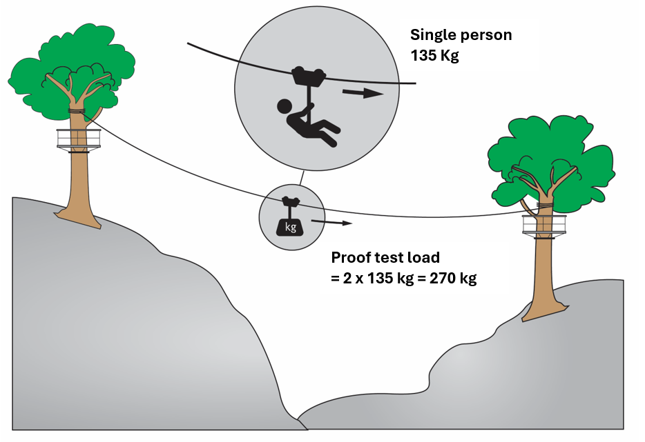
Diagram 1
Example 2
The zip line has a rated capacity of two people, one behind the other, and is based on maximum mass of each person, harness, trolley and connection hardware of 135 kg.
Proof test load = 2 x 135 = 270 kg per suspension point. 270 kg is to be suspended from one zip line trolley and 270 kg suspended from the other trolley (refer Diagram 2).
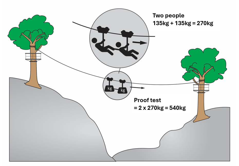
Diagram 2
Pressed ferrule rope terminations
Pressed ferrule rope terminations consist of a metal ferrule or sleeve that is pressed onto the two parts of a wire rope. The ferrules are usually attached using a fixed metal hydraulic swaging press or a cordless swaging device fitted with appropriate dies. Ferrule terminations should be provided with two swages at every rope termination. This is now a requirement of AS 2316.2.1-2025 (refer Photograph 2 for an example of two ferrules).
The design engineer is to consider potential corrosion of the rope termination which can be in the form of rust or galvanic corrosion by the combination of dissimilar metals. It is also important to monitor any die or tool wear so that the swaging pressure is not reduced.
If ferrules (swages) are fitted on site using a handheld powered tool, the tool should be a rope swaging tool approved by the manufacturer for the installation of wire rope terminations used for supporting people. The design engineer should specify the size and characteristics of the rope swage sleeves (e.g. material and type) and the swaging tool to be used. Crimping tools, designed for joining electrical cable, should not be used to construct wire rope terminations.
Documented test results relating to the tensile strength of identical rope terminations for critical lines and backup lines should be available at the zip line facility. This test is in addition to the proof testing of every zip line referred to above. The test results should provide evidence of the minimum strength of the pressed ferrule rope terminations. The test results should relate to the same press (or swaging tool), dies, rope specifications and ferrule (swage sleeve) used on the zip lines at the facility. The test documentation can be in the form of tensile strength testing carried out on a test sample and should be preferably carried out by a third party.
Wire rope grips
Some zip lines being operated in Queensland may still be using wire rope grips. AS 2316.2.1-2025 has been revised and now prohibits the use of wire rope grips on critical lines and backups used for redundancy. A critical line is defined as “primary safety cable used for participant safety, where its failure would result in an incident or system failure.” A critical line includes a zip line and includes a fall arrest line above an activity element at a high ropes course (e.g. rope bridge, lily pads, etc). Wire rope grips are not to be used on zip lines or fall arrest lines.
Reasons why wire rope grips must not be used on critical lines and backups include the following:
- Effective use requires tightening to a specific torque.
- To ensure ongoing safe operation, nuts will require re-tightening at least until the rope under the grip is stable under load (the rope diameter decreases under load).
- 'Bulldog' type wire rope grips (i.e. using a single saddle and U-bolt) will deform parts of the rope (usually the rope tail)3.
- Wire rope grips are more susceptible to tampering than pressed ferrules (i.e. they can be loosened using only a spanner).
If under-tightened, the wire rope can slip through the rope grips and cause the zip line to pull out. If over-tightened, the threads on the rope grips can be stripped so that pressure on the rope is lost and the line pulls out. If over-tightened and threads are not stripped, the rope can be damaged so that premature rope failure could potentially occur. In addition, it should be noted that the wire rope grip furthest from the eye of the thimble should not be over-tightened as that position is the most vulnerable part of the termination assembly.
Further information
- Australian Adventure Activity Standard and associated Good Practice Guides
- Australian Standard AS 1666.1:2009 Wire rope slings Part 1: Product specification
- AS 2076-1996 Wire rope grips for non-lifting applications
- AS 2759-2004 Steel wire rope – Use, operation and maintenance
Australian Standards can be obtained by contacting Standards Australia. Australian Adventure Activity Standards are available at www.australianaas.org.au.
[1] There are also other examples of acceptable termination methods that can be found in AS 2316.2.1-2025 and AS 2759-2004 Steel wire rope – Use, operation and maintenance.
[2] AS 2316.2.1-2025 specifies a mass of 135 Kg for an adult but allowance must be made for the weight of the equipment (i.e. trolley, harness, lanyard, attachment hardware and clothing).
[3] Double-throat wire rope grips are another type of wire rope grip and are designed not to damage the rope. However, their effectiveness still requires tightening and re-tightening to a minimum torque.